- Introduction
- What is the Role of Root Port in STP?
- How Does a Switch Choose the Root Port?
- Author Insight: Why Root Port Failure Matters in Real Networks
- What Happens When STP Root Port Fails?
- Step 1: The Switch Detects Loss of BPDU
- Step 2: The Existing Root Path Becomes Invalid
- Step 3: STP Checks for an Alternate Port
- Step 4: A New Root Port is Selected
- Step 5: The Port Moves Through STP States
- Step 6: STP Convergence Completes
- Author Insight: Backup Links Do Not Always Mean Fast Recovery
- STP vs RSTP Failover Timing
- STP Root Status Released Explained
- When Should You Worry About STP Root Status Released?
- Symptoms of a Spanning Tree Failure
- Possible Consequences of an STP Failure
- Author Insight: STP Problems Are Usually Design Problems
- How Do You Troubleshoot STP Issues?
- Step-by-Step STP Troubleshooting Process
- Cisco Spanning Tree Commands
- Root Guard in STP Example
- Real-World Root Guard Scenario
- Author Insight: Where Root Guard Should Be Used
- Best Practices to Prevent STP Failures
- Practical Example: Root Port Failure in a Three-Switch Network
- Common Mistakes That Make Root Port Failure Worse
- How to Know If STP Failover Worked Correctly
- FAQ
- Conclusion
Introduction
One failed cable can silently disrupt your entire network — not because a backup path doesn’t exist, but because Spanning Tree Protocol (STP) takes time to recover.
In one real-world network scenario, a distribution switch uplink went down, and within seconds users experienced VoIP drops, slow applications, and intermittent connectivity. The root cause was simple: the STP root port failed, triggering a topology recalculation.
In Spanning Tree Protocol, the root port is the primary path toward the root bridge. When it fails, the network must quickly adapt to maintain stability — but this process is not always instant.
At first, users may only notice small issues:
- A few dropped packets
- Slow application response
- VoIP call interruption
- Temporary disconnection from shared resources
When the engineer checks the switch, the issue is related to one thing: STP root port fails.
In Spanning Tree Protocol, the root port is the main path a non-root switch uses to reach the root bridge. When that port fails, STP must recalculate the topology and select another path. This process is called STP convergence.
The good news is that STP is designed to prevent Layer 2 loops. The bad news is that if STP is slow, misconfigured, or poorly designed, even a simple root port failure can cause noticeable network disruption.
Cisco explains that Spanning Tree Protocol prevents loops when switches are connected through multiple paths by exchanging BPDU messages and blocking selected interfaces to maintain a loop-free topology:
Cisco Spanning Tree Protocol Overview
In this guide, we will explain exactly what happens when an STP root port fails, how failover works, what symptoms to watch for, and how to troubleshoot STP issues like a real network engineer.
What is the Role of Root Port in STP?
The root port is the port on a non-root switch that provides the best path toward the root bridge.
In simple words:
The root port is the switch’s best way to reach the root bridge.
Every non-root switch has only one root port per STP instance. This port is normally in the forwarding state and carries traffic toward the root bridge.
If you want a deeper explanation of how the root port is selected using cost, bridge ID, and tie-breaker rules, read this detailed guide:
STP Root Port Selection Explained with Examples
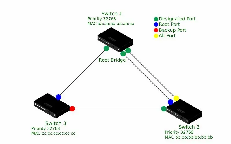
Simple STP topology showing root bridge, root port, and alternate paths in a redundant network.
How Does a Switch Choose the Root Port?
A switch does not randomly choose its root port. STP follows a clear decision process.
The switch compares:
- Lowest root path cost
- Lowest sender bridge ID
- Lowest sender port ID
- Lowest local port ID, if needed
The main goal is to choose the most efficient and loop-free path toward the root bridge.
Bridge ID plays an important role in STP decisions because it combines bridge priority and MAC address. You can learn this concept in detail here:
What is Bridge ID in STP? Priority, MAC Address & Election Process
Author Insight: Why Root Port Failure Matters in Real Networks
In real networks, root port failure is not always dramatic at first. Sometimes the backup path exists, and the network eventually recovers.
But during convergence, users can still feel the impact.
From practical network troubleshooting experience, the biggest issue is usually not the failed cable or uplink itself. The real issue is how quickly the network can recover after the failure.
For example, in one access-layer design, an uplink failure caused the switch to recalculate STP. The backup path existed, but classic STP took time to move the new port into forwarding state. During that short window, users experienced:
- VoIP jitter
- Temporary packet loss
- Slow access to internal applications
- Brief server disconnection
This is why understanding STP failover is important. A backup link is useful only when the network can activate it safely and quickly.
What Happens When STP Root Port Fails?
Root Port Failure → BPDU Loss → Alternate Path Selection → New Root Port → STP Convergence
When an STP root port fails, the switch loses its current best path to the root bridge. STP then starts a controlled recovery process.
This process includes:
- Detecting BPDU loss
- Invalidating the failed root path
- Checking alternate paths
- Selecting a new root port
- Moving the new port through STP states
- Restoring forwarding after convergence
Let’s break this down step by step.
Step 1: The Switch Detects Loss of BPDU
BPDUs, or Bridge Protocol Data Units, are control messages used by STP switches to exchange topology information.
A root port normally receives BPDUs from the upstream switch. These BPDUs help the switch understand where the root bridge is and which path is best.
When the root port fails:
- The physical link may go down
- BPDUs stop arriving
- STP information on that port becomes invalid
- The switch starts recalculating the topology
Huawei’s STP documentation also describes BPDUs as the messages used to exchange spanning tree topology information between devices:
Huawei STP Topology and BPDUs
Step 2: The Existing Root Path Becomes Invalid
After BPDU loss or link failure, the switch can no longer use the old root port as a valid path to the root bridge.
At this point:
- The old root port is removed from the active topology
- The switch clears old root path information
- STP starts searching for another valid path
This is where some logs may show messages similar to:
STP root status released
This means the switch has lost its current root relationship or root path state and is recalculating the topology.
Step 3: STP Checks for an Alternate Port
If the switch has another path toward the root bridge, STP checks whether that port can become the new root port.
This backup path may be an:
- Alternate port
- Blocked port
- Redundant uplink
In classic STP, a blocked port may need to move through listening and learning states before it can forward traffic.
In RSTP, an alternate port can often move to forwarding much faster.
This is one reason modern enterprise networks prefer RSTP instead of old 802.1D STP.
Step 4: A New Root Port is Selected
After checking available paths, the switch selects a new root port.
The selection follows normal STP rules:
- Lowest path cost wins
- If cost is equal, lower bridge ID wins
- If still tied, lower port ID wins
If you want to understand the larger election process around root bridge selection, see this guide:
Root Bridge Election Process in Cisco Switch
For a practical example of STP root bridge election, you can also read:
STP Root Bridge Election Example Explained
Step 5: The Port Moves Through STP States
In traditional STP, the new root port does not immediately begin forwarding traffic.
It normally goes through these states:
- Blocking
- Listening
- Learning
- Forwarding
STP port state transitions from blocking to forwarding during convergence.
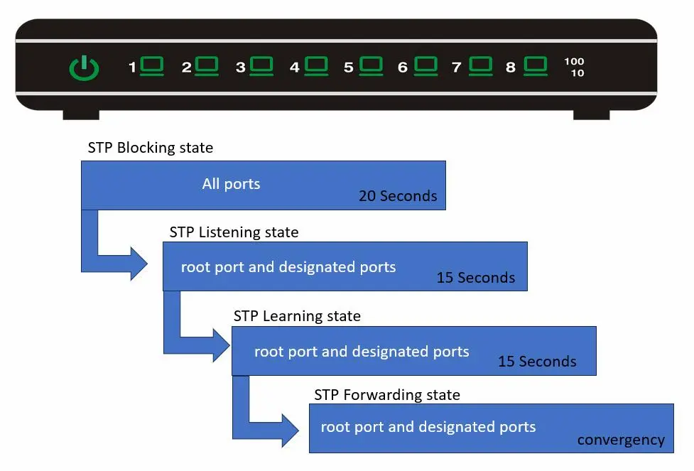
This controlled transition helps prevent Layer 2 loops.
The downside is delay. During this delay, traffic may be interrupted.
A common classic STP transition can take around 30 to 50 seconds depending on timers and topology. RSTP is much faster because it was designed for rapid convergence.
Step 6: STP Convergence Completes
STP convergence means the network has recalculated its loop-free topology and traffic can flow again.
After convergence:
- A new root port is active
- Backup path becomes the forwarding path
- Network traffic stabilizes
- MAC address tables begin updating normally
From a user perspective, the network may look normal again. But from an engineer’s perspective, it is important to check why the failure happened and whether the design handled it properly.
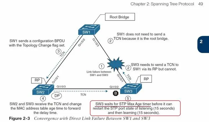
STP failover process showing how the switch detects root port failure and selects a new path.
Author Insight: Backup Links Do Not Always Mean Fast Recovery
A common mistake in network design is assuming that redundant links automatically mean high availability.
That is not always true.
If STP is not tuned properly, a backup link may exist but still take too long to become active. In real environments, this delay can affect:
- IP phones
- CCTV streams
- ERP applications
- Authentication services
- File server access
This is why failover testing is important. You should not only check whether a backup link exists. You should also test how quickly traffic recovers when the primary root port fails.
STP vs RSTP Failover Timing
In modern enterprise networks, relying on traditional STP for failover is considered inefficient due to its slow convergence time, which can impact real-time applications like VoIP and critical services.
Traditional STP and RSTP behave differently during failover.
| Feature | Traditional STP | RSTP |
|---|---|---|
| Convergence speed | Slower | Faster |
| Failover behavior | Timer-based | Proposal/agreement and rapid transition |
| Backup path activation | Slower | Faster |
| Best use | Legacy networks | Modern networks |
RSTP is usually preferred because it reduces downtime after link failure.
However, RSTP still needs correct design. A bad topology, incorrect root placement, or missing protections can still create problems.
STP Root Status Released Explained
The phrase STP root status released usually indicates that a switch has released or lost its current root status/path information.
This can happen when:
- The root port goes down
- The upstream switch fails
- BPDUs stop arriving
- A better root bridge appears
- The STP topology changes
In simple terms, the switch is saying:
My current root path is no longer valid, so I need to recalculate.
This message should not be ignored. It may be part of normal failover, but if it appears frequently, it can indicate instability.
When Should You Worry About STP Root Status Released?
You should investigate if this message appears repeatedly.
Frequent root status changes can mean:
- Flapping uplink
- Bad fiber or cable
- Misconfigured STP priority
- Rogue switch connected to the network
- Unstable trunk link
- Incorrect VLAN/STP design
If the message appears once during planned maintenance, it may be normal. But if it appears again and again, it needs troubleshooting.
Symptoms of a Spanning Tree Failure
A spanning tree failure can show many symptoms. Some are obvious, while others are hidden until the network becomes unstable.
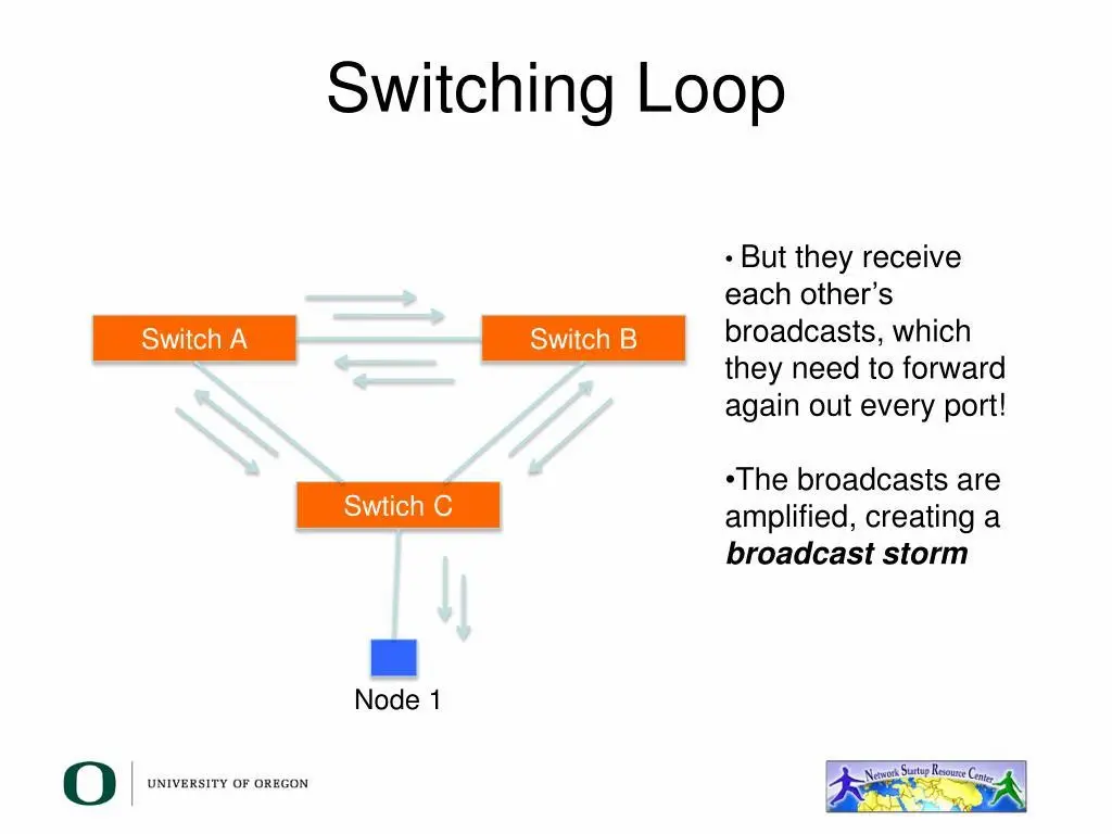
1. Broadcast Storms
A broadcast storm happens when broadcast frames keep circulating in the network.
Symptoms include:
- Very slow network
- High link utilization
- Users unable to access services
- Switch CPU increase
Broadcast storms are one of the most dangerous signs of STP failure.
2. MAC Address Table Instability
If the same MAC address keeps appearing on different ports, the switch may constantly relearn it.
This is often called MAC flapping.
Symptoms include:
- Logs showing MAC movement
- Intermittent connectivity
- Packet loss
- Unstable forwarding behavior
3. High CPU Usage
When STP fails and loops form, switches may process excessive control-plane or broadcast traffic.
This can increase CPU usage and cause the switch to become slow or unstable.
4. Intermittent Connectivity
Users may report that the network works for a few seconds and then fails again.
This can happen when:
- Links flap
- STP reconverges repeatedly
- MAC tables keep changing
- A loop appears and disappears
5. Slow Network Performance
Sometimes the network does not fully go down, but performance becomes poor.
You may notice:
- Slow file transfers
- Delayed login
- Poor VoIP quality
- Application timeout
Many STP problems are caused by configuration mistakes, and this topic is covered in detail here:
Why STP Port Misconfigurations Break Networks
Example of a broadcast storm caused by a loop when STP fails or is misconfigured.
Possible Consequences of an STP Failure
The possible consequences of an STP failure can be serious, especially in production networks.
Network Downtime
If STP cannot create a stable loop-free topology, parts of the network may become unreachable.
Packet Loss
During convergence, packets may be dropped because the forwarding path is changing.
Performance Degradation
Even if the network stays online, users may experience slow applications and poor response time.
Layer 2 Loops
This is the worst-case scenario. A loop can cause frames to circulate endlessly.
Broadcast Storms
A broadcast storm can consume bandwidth and overwhelm switches.
Business Impact
For a business, this can mean:
- Lost productivity
- Failed transactions
- Dropped calls
- Customer service interruption
- Monitoring alerts and escalation
Author Insight: STP Problems Are Usually Design Problems
In real troubleshooting, STP problems are often not caused by the protocol itself.
They usually come from:
- Default root bridge selection
- No root guard
- Wrong PortFast usage
- Missing BPDU Guard
- Poor VLAN design
- Uncontrolled switch connections
STP works well when the network is designed properly. It becomes dangerous when the topology is left to chance.
How Do You Troubleshoot STP Issues?
Troubleshooting STP issues requires a structured approach. Do not start changing settings randomly.
Think like a network engineer:
- Identify the root bridge
- Find the root port
- Check port roles and states
- Look for topology changes
- Check logs
- Verify protection features
- Confirm physical stability
Huawei’s STP troubleshooting guidance also recommends checking whether the connected device configuration changed or whether STP BPDUs are being transparently transmitted:
Huawei Troubleshooting STP
Step-by-Step STP Troubleshooting Process
Step 1: Identify the Root Bridge
First, confirm which switch is currently acting as the root bridge.
Use:
show spanning-tree root
Check whether the expected core or distribution switch is root.
If an access switch becomes root unexpectedly, your STP design is wrong.
Step 2: Check the Root Port
Use:
show spanning-tree
Look for the root port on the non-root switch.
Check:
- Is the root port up?
- Is it forwarding?
- Has the root port changed recently?
- Is the path cost expected?
Step 3: Check Port Roles and States
Look for ports in:
- Root
- Designated
- Alternate
- Blocking
- Forwarding
- Learning
Unexpected forwarding ports may indicate a loop risk.
Unexpected blocking ports may indicate a topology or cost issue.
Step 4: Look for Topology Changes
Frequent topology changes are a strong sign of instability.
Look for:
- Link flaps
- Root port changes
- MAC flapping
- STP recalculation messages
Step 5: Check Physical Links
Do not ignore the physical layer.
Check:
- Fiber modules
- Copper cables
- Patch panels
- Trunk ports
- Interface errors
- Duplex/speed mismatch
Many STP reconvergence events are triggered by unstable physical links.
Step 6: Review Logs
Check logs for:
- Root changes
- BPDU Guard events
- Root Guard events
- Interface flapping
- Topology change notifications
Use:
debug spanning-tree events
Use debug carefully in production networks because it may increase CPU load.
Step 7: Verify Protection Features
Check whether these features are configured correctly:
- Root Guard
- BPDU Guard
- PortFast
- Loop Guard
- UDLD, where needed
Cisco explains that BPDU Guard helps improve reliability, manageability, and security by protecting PortFast-enabled ports from unexpected BPDU reception:
Cisco PortFast BPDU Guard Documentation
From practical experience, even when a backup path exists, slow STP convergence can still cause temporary service disruption, especially in environments running real-time applications.
Cisco Spanning Tree Commands
Here are useful Cisco spanning tree commands for troubleshooting.
1. show spanning-tree
show spanning-tree
This command displays:
- VLAN STP details
- Root bridge
- Bridge ID
- Root port
- Port roles
- Port states
Use this as your first command when investigating STP behavior.
2. show spanning-tree root
show spanning-tree root
This command shows which switch is the root for each VLAN or instance.
Use it to confirm whether the correct switch is root.
3. show spanning-tree vlan
show spanning-tree vlan 10
This command checks STP details for a specific VLAN.
It is useful in PVST environments where each VLAN can have a different root bridge.
For more detail on VLAN-based spanning tree behavior, read:
PVST Election Process Explained with Examples
4. debug spanning-tree events
debug spanning-tree events
This command shows STP events in real time.
It can help identify:
- Port transitions
- Root changes
- Topology changes
- BPDU-related events
Use it carefully on production switches.
5. show logging
show logging
This command helps you review historical STP-related events.
Look for messages related to:
- Root changes
- Link flaps
- BPDU Guard
- Root Guard
- Interface state changes
Root Guard in STP Example
Root Guard is used to protect the intended root bridge from being replaced by an unexpected switch.
Cisco describes Root Guard as a feature that improves STP reliability and manageability by preventing unexpected devices from becoming the root bridge:
Cisco Root Guard Documentation
Root Guard preventing an unauthorized switch from becoming the root bridge.

Real-World Root Guard Scenario
Imagine your network design is:
- Core Switch = intended root bridge
- Distribution Switch = secondary root
- Access Switches = should never become root
Now someone connects a new switch to an access layer port.
That new switch has a lower bridge priority and sends superior BPDUs.
Without Root Guard:
- The new switch may become root
- Traffic paths may change
- STP topology may reconverge
- Network performance may suffer
With Root Guard:
- The port detects superior BPDU
- The port moves into root-inconsistent state
- The unexpected switch cannot become root
- Your STP design remains stable
Author Insight: Where Root Guard Should Be Used
In practical enterprise designs, Root Guard is commonly used on ports where you never expect a root bridge to appear.
For example:
- Access switch uplinks facing downstream switches
- Ports connected to unmanaged areas
- Customer-facing switch ports in provider environments
- Edge areas where someone might connect an unknown switch
Root Guard should not be placed randomly. It should be used where the root bridge should never be learned from that direction.
Best Practices to Prevent STP Failures
1. Manually Define the Root Bridge
Do not let the network choose the root bridge automatically.
Set the core switch as the primary root and another stable switch as the secondary root.
This creates predictable traffic flow.
2. Use RSTP Instead of Traditional STP
RSTP provides faster convergence than classic STP.
If your environment supports it, RSTP is usually a better choice.
3. Configure BPDU Guard on Edge Ports
Access ports connected to end devices should not receive BPDUs.
If a BPDU appears on an access port, it may indicate that someone connected a switch where they should not.
BPDU Guard helps shut down that risk.
4. Use Root Guard in the Right Places
Root Guard helps protect your intended root bridge.
Use it on ports where superior BPDUs should never be received.
5. Avoid Unplanned Layer 2 Extensions
Large Layer 2 domains are harder to control.
Keep VLANs and Layer 2 designs clean and intentional.
6. Monitor Topology Changes
Frequent STP topology changes are a warning sign.
Monitor:
- Root changes
- Port state changes
- MAC flapping
- Link flaps
- CPU spikes
7. Document Your STP Design
Your documentation should include:
- Primary root bridge
- Secondary root bridge
- Root ports
- Blocked or alternate links
- VLAN-to-root mapping
- Protection features
Good documentation makes troubleshooting much faster during outages.
8. Test Failover Before Production Problems Happen
Do not wait for a real outage.
Test:
- Root port failure
- Uplink failure
- Root bridge failover
- Backup path activation
- RSTP recovery time
This confirms whether your design works as expected.
Practical Example: Root Port Failure in a Three-Switch Network
Let’s use a simple topology:
- SW1 = Root Bridge
- SW2 = Access Switch
- SW3 = Backup path switch
SW2 has two paths:
- Direct link to SW1
- Backup link through SW3
Normally, SW2 uses its direct link to SW1 as the root port.
Now the direct link fails.
What happens?
- SW2 stops receiving BPDUs on the root port
- STP invalidates the old root path
- SW2 checks its backup path through SW3
- STP compares path cost
- SW2 selects a new root port
- New port transitions toward forwarding
- Traffic resumes after convergence
In RSTP, this process can be very fast if the alternate path is already known and valid.
In classic STP, users may feel a temporary outage.
Common Mistakes That Make Root Port Failure Worse
Mistake 1: Leaving Default Bridge Priority
If all switches use default priority, the root bridge may be selected based on MAC address.
That is risky because the wrong switch can become root.
Mistake 2: No Secondary Root Bridge
If the primary root fails and there is no planned secondary root, STP may choose an unexpected switch.
Mistake 3: No BPDU Guard on Access Ports
An unauthorized switch can send BPDUs and affect the topology.
Mistake 4: No Root Guard
Without Root Guard, a downstream switch may become root if it sends superior BPDUs.
Mistake 5: Ignoring Link Flaps
A flapping root port can cause repeated convergence events.
This creates unstable network behavior.
How to Know If STP Failover Worked Correctly
After failover, check:
- New root port is selected
- Correct root bridge remains active
- No unexpected root changes occurred
- No broadcast storm is present
- MAC table is stable
- Users can access services normally
- Logs do not show repeated topology changes
If the network recovers but keeps changing root ports, the issue is not fully resolved.
FAQ
What happens when STP root port fails?
When an STP root port fails, the switch loses its best path to the root bridge. It then checks alternate paths, selects a new root port, and reconverges the topology.
What is the role of root port in STP?
The root port is the best path from a non-root switch toward the root bridge. It is normally the forwarding port used to reach the root bridge.
What does STP root status released mean?
STP root status released means the switch has lost or released its current root path information and is recalculating the topology.
What are the symptoms of a spanning tree failure?
Common symptoms include broadcast storms, MAC address flapping, high CPU usage, packet loss, intermittent connectivity, and slow network performance.
What are the possible consequences of an STP failure?
Possible consequences include network downtime, packet loss, performance degradation, Layer 2 loops, and broadcast storms.
How do you troubleshoot STP issues?
Start by checking the root bridge, root port, port roles, port states, topology changes, logs, and physical link stability. Use commands like show spanning-tree and show spanning-tree root.
Which Cisco spanning tree commands are useful?
Useful commands include:
show spanning-tree
show spanning-tree root
show spanning-tree vlan 10
debug spanning-tree events
show logging
What is Root Guard in STP?
Root Guard prevents an unexpected switch from becoming the root bridge. If a superior BPDU is received on a Root Guard-enabled port, the port is blocked in a root-inconsistent state.
Is RSTP better than STP for failover?
Yes. RSTP usually provides much faster convergence than traditional STP, which makes it better for modern switched networks.
What happens to traffic during STP failover?
During STP failover, traffic may be temporarily dropped while the switch recalculates topology and transitions the new root port into forwarding state.
Why does STP take 30–50 seconds to converge?
STP uses multiple port states (blocking, listening, learning, forwarding) to prevent loops, which introduces delay during topology changes.
How can you reduce STP convergence time?
You can reduce convergence time by using RSTP instead of traditional STP and enabling features like PortFast, BPDU Guard, and proper root bridge placement.
Conclusion
When an STP root port fails, the switch does not simply stop working. It starts a failover process to find another valid path to the root bridge.
The process includes:
- BPDU loss detection
- Root path invalidation
- Alternate path evaluation
- New root port selection
- Port state transition
- STP convergence
In a well-designed network, this process restores connectivity safely. In a poorly designed network, it can cause downtime, packet loss, broadcast storms, and unstable performance.
In the next guide, we’ll break down how STP port states impact failover speed and convergence behavior.
The key lesson is simple:
STP failover is only as good as your STP design.
STP does not fail — it behaves exactly as designed. The real problem occurs when networks are not designed with failure scenarios in mind.
A well-designed STP topology ensures that even when the root port fails, the network recovers quickly and continues to operate efficiently without major disruption.
Abdul Shakoor writes practical, defensive cybersecurity and networking guides for SentrixHub. He focuses on making API security, mobile app security, authentication, and network concepts simple for beginners and developers.