Introduction
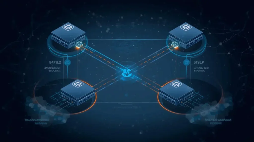
Modern enterprise networks depend heavily on redundancy.
Multiple uplinks, backup paths, distribution switches, and interconnected access layers are all designed to improve availability. But without proper Layer 2 loop prevention, redundancy can quickly become dangerous.
This is where Spanning Tree Protocol (STP) becomes critical.
Traditional STP was designed to prevent switching loops, but in many modern environments, its slow convergence behavior creates operational problems of its own. Slow failover during topology changes can interrupt production traffic, affect VoIP calls, delay application connectivity, and create instability across entire VLANs.
This is one reason why many engineers now prefer Rapid Spanning Tree Protocol (RSTP).
Understanding Serious STP Failures That RSTP Prevents Automatically is important for:
- CCNA students
- Enterprise network engineers
- Infrastructure teams
- Data center administrators
Because in real switching environments, convergence speed directly affects uptime.
💡 Author Insight
In modern enterprise environments, users often notice convergence problems before engineers notice physical failures.
🔧 Practical Observation
In many enterprise switching environments, STP instability does not appear during normal traffic conditions. Problems usually become visible during:
- uplink failures
- switch reloads
- maintenance windows
- topology recalculations
This is why many Layer 2 problems remain hidden until redundancy is actually tested.
What Problems Does STP Prevent?
👉 What problems does the Spanning Tree Protocol (STP) prevent?
STP exists primarily for:
STP network loop prevention
Without STP, redundant Layer 2 links can create catastrophic switching loops.
Layer 2 Loops
A Layer 2 loop occurs when Ethernet frames circulate endlessly between switches.
Unlike Layer 3 packets, Ethernet frames do not contain a TTL field to stop looping traffic automatically.
This creates:
- uncontrolled frame replication
- excessive broadcast traffic
- switching instability
How STP Prevents Layer 2 Loops
STP prevents switching loops by blocking redundant paths and maintaining a stable Layer 2 topology.
Broadcast Storms
Broadcast traffic becomes extremely dangerous during loops.
A single broadcast frame can replicate continuously across multiple switches until:
- switch CPUs spike
- interfaces become congested
- users lose connectivity
In real enterprise networks, broadcast storms often affect:
- IP phones
- wireless controllers
- DHCP services
- servers
- authentication traffic
Broadcast Storms During STP Failure

Without proper STP operation, Layer 2 loops can rapidly escalate into destructive broadcast storms.
💡 Author Insight
In production environments, Layer 2 loops are usually far more disruptive than beginners expect because the impact spreads across switches almost immediately.
MAC Address Table Instability
One common troubleshooting symptom engineers notice during STP instability is:
MAC flapping
The same MAC address rapidly appears on multiple interfaces because frames loop across redundant paths.
This causes:
- forwarding confusion
- intermittent connectivity
- unstable switching behavior
🔧 Practical Observation
In many switching environments, engineers first notice MAC flapping warnings long before users report complete outages.
Duplicate Frames
Loops can also create duplicate Ethernet frames.
Applications sensitive to timing — especially VoIP and real-time traffic — often experience:
- jitter
- packet duplication
- call interruptions
Switching Instability
In severe cases:
- switches become overloaded
- topology changes increase rapidly
- CPU utilization spikes
This is one reason Cisco strongly recommends proper STP design in enterprise switching environments:
What Happens When STP Fails?
👉 What are the possible consequences of an STP failure?
The effects can be severe.
Early Signs of STP Instability
Before a major Layer 2 outage occurs, switches often show early warning signs that experienced engineers recognize during troubleshooting.
- MAC flapping logs
- Frequent topology changes
- Random VoIP clipping
- Slow switch management access
- Intermittent VLAN instability
- Temporary packet loss during failover
- High switch CPU usage
In many enterprise environments, these symptoms appear briefly during topology instability and disappear before users can clearly describe the problem.
Network Outages
A major Layer 2 loop can quickly impact an entire VLAN.
In production networks, this may interrupt:
- internal applications
- IP telephony
- ERP systems
- wireless authentication
- internet connectivity
Broadcast Storms
Broadcast storms are one of the most dangerous STP failure scenarios.
Traffic replication increases exponentially until switches become overwhelmed.
High CPU Usage
Engineers often notice:
- switch CPU spikes
- management access delays
- unstable CLI responsiveness
during severe STP instability.
🔧 Troubleshooting Indicator
One hidden sign beginners often ignore is unusually slow switch management access during topology instability.
Packet Loss
As switching tables constantly update during topology instability:
- packets get dropped
- forwarding becomes inconsistent
- sessions disconnect unexpectedly
VoIP Interruptions
Voice traffic is highly sensitive to convergence delays.
Even short STP interruptions may cause:
- dropped calls
- audio clipping
- SIP registration problems
💡 Author Insight
One unstable Layer 2 segment can quickly affect VoIP, wireless connectivity, and server communication across multiple VLANs.
Entire VLAN Instability
A single Layer 2 loop inside one VLAN can destabilize large portions of the switching environment.
Root Bridge Instability
Poor STP design sometimes causes unintended root bridge changes.
This leads to:
- topology recalculations
- traffic path changes
- convergence delays
If you are still learning how root bridge selection works, read:
Root Bridge Election Process Explained
Root Bridge Instability in Switching Networks

Unexpected root bridge changes can trigger topology recalculations and unstable forwarding behavior across the network.
💡 Author Insight
In poorly planned switching environments, unexpected root bridge changes often create instability that appears random to end users.
Slow Recovery During Link Failures
One of the biggest operational limitations of traditional STP is:
slow failover recovery
This is where RSTP becomes extremely valuable.
Why Traditional STP Becomes a Problem
Traditional STP was designed for older switching environments.
Modern enterprise networks demand much faster recovery times.
⚠️ Common Beginner Mistake
Many beginners think STP only matters during loops, but most enterprise issues appear during failover and topology recalculation events.
This is one reason many engineers focus heavily on convergence testing in enterprise switching environments.
STP Convergence Time
👉 What is STP convergence time?
Traditional STP convergence may take:
- 30 to 50 seconds
depending on topology and timer behavior.
This happens because ports move through multiple transitional states before forwarding traffic.
Listening and Learning Delays
STP ports must pass through:
- Listening
- Learning
before entering Forwarding state.
These delays exist to prevent loops, but they also slow recovery significantly.
If you want deeper understanding of timer behavior, read:
Dangerous STP Timer Mistakes Beginners Make
💡 Author Insight
Traditional STP was designed for older switching environments where convergence speed was less critical than it is in modern enterprise networks.
🔧 Practical Observation
In real enterprise environments, users often interpret STP convergence delays as “network outages” even when the protocol is technically functioning correctly.
Operational Limitations in Large Networks
Large scalable Layer 2 environments create additional challenges:
- more topology changes
- larger STP domains
- slower recalculation
- increased instability risk
🔍 Hidden Problem Beginners Ignore
Many beginners focus only on redundancy and fail to realize that larger Layer 2 domains also increase convergence complexity.
Rapid Spanning Tree Protocol Explained
👉 Rapid Spanning Tree Protocol explained
RSTP (IEEE 802.1w) was developed to solve many limitations of traditional STP.
Its main goal:
Watch: How RSTP Converges Faster Than Traditional STP
This visual explanation demonstrates how Rapid Spanning Tree Protocol (RSTP) reacts much faster than traditional STP during topology changes and link failures.
In enterprise environments, this faster convergence behavior can significantly reduce user disruption during uplink failures and topology changes.
faster convergence and improved failover behavior
How RSTP Improves Convergence
RSTP dramatically reduces recovery time during:
- link failures
- topology changes
- switch transitions
In many environments:
STP vs RSTP Convergence Comparison
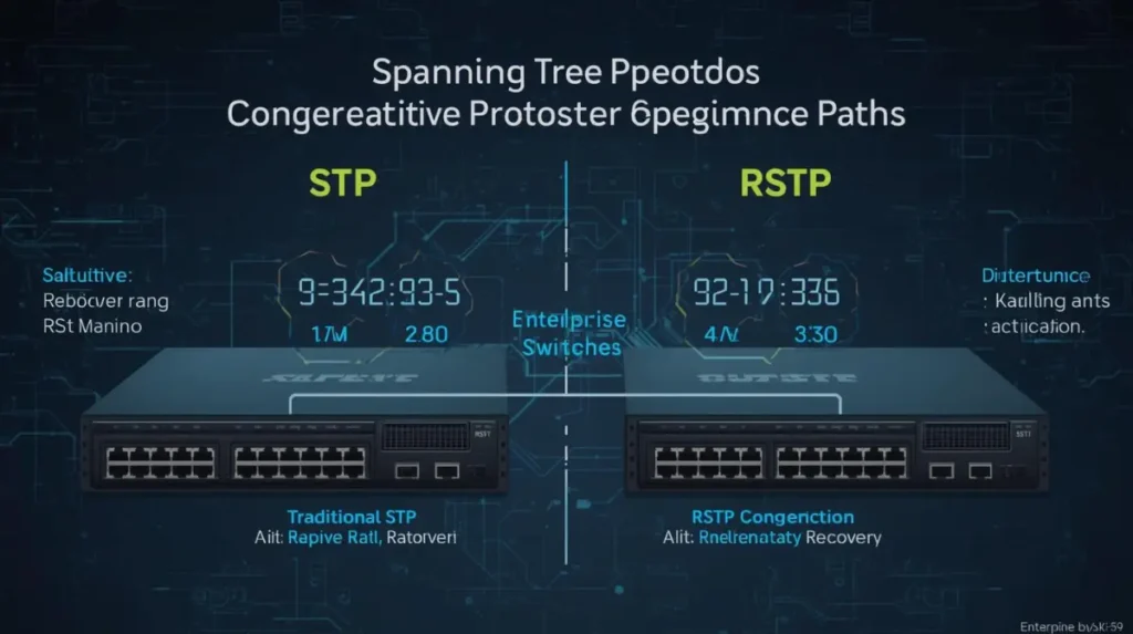
RSTP significantly reduces convergence delays by activating alternate paths much faster than traditional STP.
RSTP failover time is nearly immediate
compared to traditional STP delays.
According to several convergence studies, RSTP reacts significantly faster than legacy STP during topology events:
understanding STP and RSTP convergence
💡 Author Insight
Faster convergence is not only about speed — it is about reducing user disruption during topology changes and link failures.
Proposal and Agreement Mechanism
RSTP uses a faster synchronization process called:
- Proposal
- Agreement
Instead of waiting through long timer-based transitions, switches negotiate forwarding behavior much more efficiently.
Alternate and Backup Ports
RSTP introduces:
- Alternate Ports
- Backup Ports
These standby paths allow switches to react much faster when failures occur.
Example RSTP Port Roles
The following RSTP output shows how switches identify forwarding and alternate ports during normal topology operation.
Switch# show spanning-tree

VLAN0001
  Spanning tree enabled protocol rstp
  Root ID    Priority    4097
             Address     001b.2bff.a100
             This bridge is the root

Interface        Role Sts Cost      Prio.Nbr Type
---------------- ---- --- --------- -------- --------------------------------
Gi0/1            Desg FWD 4         128.1    P2p
Gi0/2            Altn BLK 4         128.2    P2p
Gi0/3            Desg FWD 4         128.3    Edge P2p
Notice how Gi0/2 is placed in Alternate Blocking state and can rapidly transition during uplink failure.
Rapid Failover Using Alternate Ports
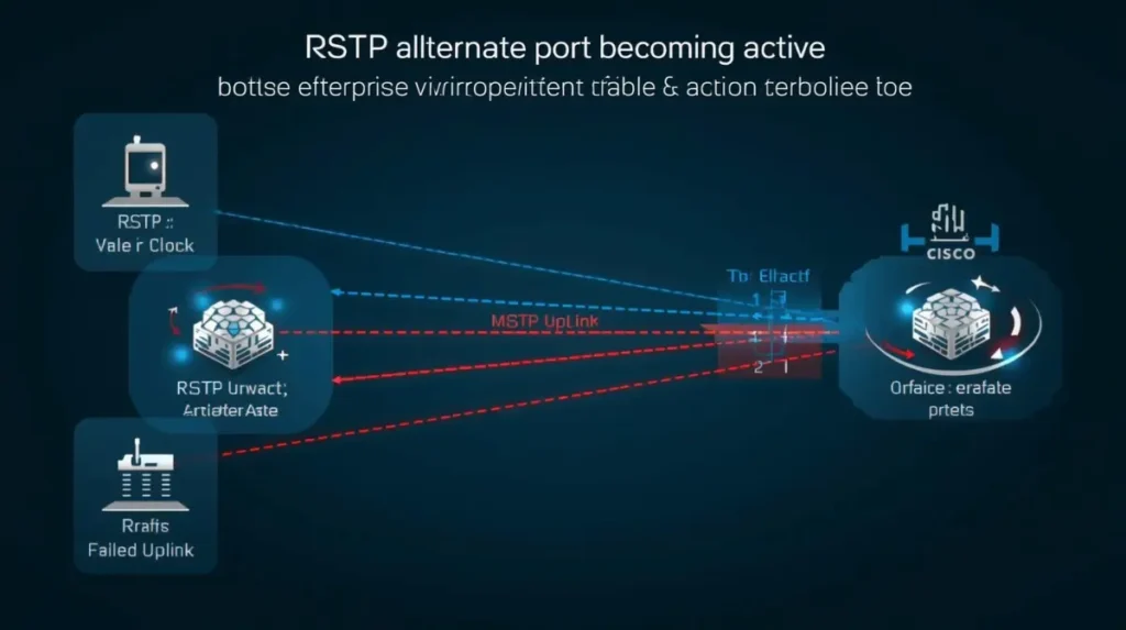
RSTP alternate ports allow switches to recover quickly during link failures without long timer-based delays.
🔧 Practical Observation
In many enterprise switching environments, alternate ports are one of the main reasons failover becomes almost unnoticeable to end users.
Edge Ports
RSTP also introduces:
Edge Ports
These ports transition rapidly into forwarding state because they connect to end devices rather than switches.
This behavior is similar to Cisco PortFast.
Serious STP Failures That RSTP Prevents Automatically
This is where the real operational difference becomes obvious.
Slow Failover Recovery
Traditional STP reacts slowly during uplink failures.
RSTP dramatically reduces downtime by activating alternate paths almost immediately.
🔧 Operational Impact
In production networks, slow failover recovery can interrupt:
- VoIP traffic
- wireless authentication
- financial applications
- remote desktop sessions
even if the outage lasts only a few seconds.
Long Convergence Delays
RSTP vs STP convergence behavior is one of the biggest improvements in modern switching.
RSTP avoids many lengthy transitional delays used by legacy STP.
Temporary Network Outages
During topology recalculation, traditional STP may temporarily interrupt forwarding.
RSTP minimizes these interruptions significantly.
🔍 Failure Pattern Recognition
A common pattern engineers notice during STP instability is that outages appear briefly during failover and then disappear before users can fully explain the issue.
Switching Loops After Topology Changes
RSTP reacts faster to topology changes, reducing the risk of temporary loop conditions during failover events.
Delayed Forwarding States
Traditional STP spends considerable time in:
- Listening
- Learning
RSTP streamlines these transitions.
If you are learning how STP forwarding and blocking behavior works, read:
Why One Switch Port Forwards While Another Blocks in STP
Root Bridge Instability
RSTP responds much faster to root bridge failures and topology recalculations.
This improves overall network stability.
Excessive Downtime During Link Failure
One failed uplink in traditional STP may create noticeable interruption.
RSTP significantly reduces recovery time.
💡 Comparative Insight
Traditional STP focuses heavily on loop prevention through timer-based waiting, while RSTP focuses more on rapid topology awareness and faster recovery behavior.
Enterprise Traffic Disruption
Production traffic such as:
- VoIP
- wireless authentication
- ERP traffic
- storage communication
benefits heavily from faster convergence.
Broadcast Storm Escalation
Faster topology handling reduces the chance of broadcast storms escalating during instability events.
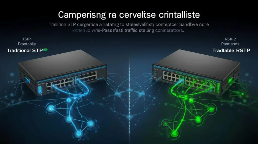
STP vs RSTP Comparison
| Feature | Traditional STP | RSTP |
|---|---|---|
| Convergence Speed | Slow | Fast |
| Failover Behavior | Timer-based delays | Rapid recovery |
| Port States | More transitional states | Simplified behavior |
| Scalability | Limited in large networks | Better enterprise scalability |
| Enterprise Suitability | Older environments | Modern enterprise networks |
| Recovery Speed | 30–50 seconds possible | Often sub-second to few seconds |
| Network Stability | Slower recalculation | Faster stabilization |
| CPU / Network Impact | Higher during instability | Reduced convergence overhead |
STP:
- Listening
- Learning
- Forwarding
- 30–50 sec
VS
RSTP:
- rapid forwarding
- alternate port activation
- few seconds
Can RSTP Work with STP?
👉 Can RSTP work with STP?
Yes.
RSTP is backward compatible with traditional STP.
In mixed environments:
- RSTP detects legacy STP neighbors
- compatibility mode activates automatically
However:
- convergence behavior may slow down
- legacy STP limitations may still affect portions of the network
🔧 Practical Observation
In mixed STP/RSTP environments, engineers sometimes assume convergence will remain fully rapid, but legacy STP devices often slow down portions of the topology.
Why RSTP Is Faster Than STP
👉 Why RSTP is faster than STP
Several technical improvements make RSTP faster:
- Faster topology detection
- Proposal/agreement synchronization
- Alternate ports
- Reduced dependency on timer delays
- Rapid forwarding transitions
This allows RSTP to recover from failures much more efficiently.
A practical engineering explanation of rapid failover behavior is also discussed here:
Why Is RSTP Faster Than STP?
RSTP is faster because it:
- uses alternate ports
- reduces timer dependency
- detects topology changes faster
- activates forwarding paths rapidly
💡 Performance Observation
In many enterprise environments, the difference between STP and RSTP becomes most noticeable during uplink failures rather than during normal traffic operation.
Rapid Spanning Tree Protocol (RSTP)
Real Enterprise Scenario
Consider a campus network with:
- redundant uplinks
- multiple access switches
- VoIP phones
- wireless access points
An uplink between an access switch and distribution switch fails unexpectedly.
Enterprise Failover Using RSTP

RSTP rapidly restores connectivity during uplink failures, helping minimize disruption to enterprise traffic and real-time applications.
Traditional STP Behavior
- ports begin timer-based transitions
- convergence delay occurs
- VoIP calls drop temporarily
- users lose connectivity briefly
RSTP Behavior
- alternate path activates rapidly
- minimal interruption occurs
- voice traffic stabilizes quickly
💡 Author Insight
Modern enterprise networks rely heavily on fast failover because even short interruptions can affect voice traffic, authentication systems, and real-time applications.
🔧 Enterprise Environment Observation
In many enterprise switching environments, users may not even notice an uplink failure when RSTP is configured correctly.
Best Practices for RSTP Deployments
Root Bridge Planning
Always control root bridge placement intentionally.
Use BPDU Guard
Protect edge ports from accidental switch connections.
Configure PortFast / Edge Ports
Improve endpoint connectivity speed safely.
Design Proper Redundant Uplinks
Avoid uncontrolled Layer 2 complexity.
Monitor Topology Changes
Frequent topology changes often indicate:
- instability
- loops
- misconfiguration
Test Failover Scenarios
Many engineers only discover convergence problems during real outages.
Regular failover testing is critical.
💡 Design Recommendation
Stable Layer 2 design is usually achieved through predictable topology behavior rather than aggressive optimization attempts.
💡 Design Mindset
Modern enterprise switching design focuses less on simply preventing loops and more on maintaining predictable failover behavior during topology changes.
FAQs
What problems does the Spanning Tree Protocol (STP) prevent?
STP prevents:
- Layer 2 loops
- broadcast storms
- MAC table instability
- duplicate frames
- switching instability
Can RSTP work with STP?
Yes. RSTP is backward compatible with traditional STP and can operate in mixed switching environments.
What are the possible consequences of an STP failure?
Possible consequences include:
- network outages
- broadcast storms
- packet loss
- VoIP interruptions
- VLAN instability
- root bridge instability
What is RSTP used for preventing?
RSTP is primarily used for:
- faster loop prevention
- rapid failover
- reducing convergence delays
- improving Layer 2 network stability
Why is RSTP faster than STP?
RSTP uses:
- faster topology detection
- alternate ports
- rapid synchronization
- reduced timer dependency
which improves failover speed significantly.
What is STP convergence time?
Traditional STP convergence may take 30–50 seconds depending on topology and timer behavior.
Why Modern Networks Prefer RSTP
Faster convergence and improved topology stability make RSTP a preferred choice for modern enterprise switching environments.
Final Conclusion
Understanding Serious STP Failures That RSTP Prevents Automatically is extremely important in modern enterprise networking.
Traditional STP successfully prevents loops, but its slow convergence creates operational risks during:
- topology changes
- uplink failures
- switch instability
RSTP solves many of these problems by:
- improving failover speed
- reducing convergence delays
- stabilizing switching behavior
- minimizing production downtime
💡 Final Engineering Insight
In modern switching environments, fast convergence is no longer a luxury feature — it is part of maintaining reliable enterprise connectivity.
For modern enterprise environments, Rapid Spanning Tree Protocol is no longer just an optimization — it is often a practical requirement for maintaining stable and resilient Layer 2 infrastructure.
Abdul Shakoor writes practical, defensive cybersecurity and networking guides for SentrixHub. He focuses on making API security, mobile app security, authentication, and network concepts simple for beginners and developers.