
If you have ever spent an afternoon staring at a show spanning-tree output trying to figure out why traffic is taking the “wrong” path, you already know that root port selection is one of those topics that looks simple on a whiteboard and gets messy the moment real hardware, real cabling, and real VLANs get involved.
I have configured and troubleshot STP on more Cisco Catalyst switches than I can count, and the pattern is always the same: teams understand the theory but get caught off guard the first time a switch picks a root port that “shouldn’t” win. This guide walks through exactly how root port selection works, with the same decision order Cisco switches actually use, plus the mistakes that cause real outages.
What Is a Root Port?
A root port is the single port on every non-root switch that offers the lowest-cost path back to the root bridge. Every switch in the topology — except the root bridge itself — elects exactly one root port, and that port becomes the primary route for all traffic heading toward the root.
Root port selection only makes sense once you understand how the root bridge itself gets chosen in the first place. If that part is still fuzzy, it’s worth reviewing the root bridge election process on a Cisco switch before going further, since the root port calculation depends entirely on which switch wins that election.
📌 Field Note: On a lab topology with two or three switches, spotting the root port is almost trivial. On a distribution-layer network with five or six redundant uplinks, I have watched senior engineers guess wrong because they assumed “closest” meant “cheapest.” STP doesn’t care about physical proximity — only cost.
How Root Port Selection Works (Cisco’s Decision Order)
Cisco switches evaluate root port candidates using a strict, three-step tiebreaker sequence. Each step only gets checked if the previous one ends in a tie.
1. Lowest Path Cost
Every link has a cost based on its speed, and the switch adds up the cumulative cost of every hop back to the root bridge.
| Speed | STP Cost |
|---|---|
| 10 Mbps | 100 |
| 100 Mbps | 19 |
| 1 Gbps | 4 |
| 10 Gbps | 2 |
The port with the lowest total path cost to the root wins, full stop.
2. Lowest Bridge ID
If two candidate paths tie on cost, the switch compares the Bridge ID of the neighboring switch sending the BPDU. For a full breakdown of how this value is built and why it matters, see what Bridge ID actually means in STP.
3. Lowest Port ID
If cost and Bridge ID are both tied, the switch falls back to the lowest port ID on the neighboring switch — usually the physically lower-numbered interface.
To see this same cost-comparison process applied live on a multi-switch topology, the video below walks through root port selection step by step:
Watch: A step-by-step walkthrough of root port selection across a multi-switch STP topology.
⚠️ Common Pitfall: I have seen this exact scenario play out with stacked switches where a member switch’s port ID formatting doesn’t behave the way engineers expect at the tiebreaker stage, which is exactly why relying on cost alone (and configuring it explicitly) saves headaches later instead of trusting default tiebreakers to land where you assume they will.
Root Port Selection Example (Real Scenario)
Here’s a topology I’ve used to walk junior engineers through this exact decision:
        Switch A (Root)
         /          \
   cost 4         cost 19
     /              \
Switch B ----------- Switch C
         cost 4
On Switch C, there are two possible paths back to the root:
- Direct link to Switch A → cost 19
- Path through Switch B → cost 4 + 4 = 8
STP always picks the lower cumulative cost, so Switch C’s root port ends up being the interface facing Switch B — not the direct link to the root, even though the direct link looks like the obvious choice on paper.
For a companion walkthrough that covers the root bridge side of this same kind of topology, check the STP root bridge election example.
Here’s how that cost comparison looks when mapped onto the actual topology:
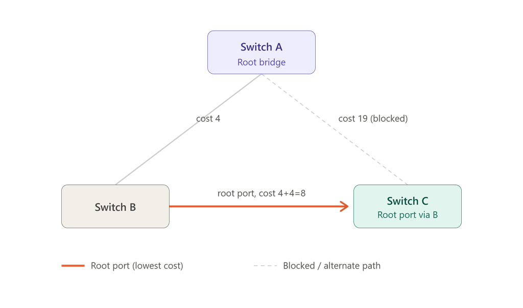
Switch C’s direct link to the root costs 19, but the path through Switch B totals only 8 — so the root port forms on the B-facing interface instead.
How to Check the Root Port (Cisco Commands)
To verify root port selection on a live switch, run:
show spanning-tree
Example output:
Interface        Role Sts Cost
Fa0/1            Root FWD 4
Fa0/2            Desg FWD 19
Here, Fa0/1 is the root port. If you’re unfamiliar with why Cisco interfaces are labeled this way, the naming convention is explained in what FastEthernet0/0 (Fa0) actually refers to.
✅ Quick Check: This command should be the very first thing you run when troubleshooting an unexpected traffic path. In practice, it takes about five seconds and tells you immediately whether the switch’s root port matches what your topology diagram says it should be — and when it doesn’t, that mismatch is usually the whole problem.
Root Port vs. Designated Port
These two roles get confused constantly, especially by people newer to switching.
| Feature | Root Port | Designated Port |
|---|---|---|
| Direction | Toward the root bridge | Away from the root bridge |
| Function | Provides the best path in | Forwards traffic out on a segment |
| Count per switch | Exactly one (except root bridge) | One per segment |
In VLAN-based Cisco environments, this gets an extra layer because each VLAN runs its own instance. The PVST election process explains how root and designated ports can actually differ from VLAN to VLAN on the same physical switch. It’s also worth understanding why only one switch port ends up forwarding on a shared segment — that behavior is a direct consequence of designated port election.
Configuring the Root Bridge Manually
Leaving root bridge selection to chance is one of the more common design mistakes I run into during audits. To force a specific switch to win the election:
spanning-tree vlan 1 root primary
or, to set it manually with a specific priority value:
spanning-tree vlan 1 priority 24576
📌 Field Note: I’ve walked into networks where the “root bridge” was whichever switch happened to have the lowest MAC address by accident — often an access-layer switch in a wiring closet, not the core. Nobody had configured root primary when the network was built, so every topology change afterward recalculated paths through a device that was never meant to carry that load. Setting this explicitly during initial deployment prevents that entirely.
STP vs. RSTP vs. PVST vs. MSTP
| Protocol | Convergence | Typical Use |
|---|---|---|
| STP (802.1D) | Slow (30–50s) | Legacy networks |
| RSTP (802.1w) | Fast (sub-second to a few seconds) | Modern deployments |
| PVST+ | Medium, per-VLAN | Cisco VLAN environments |
| MSTP (802.1s) | Fast, grouped instances | Large enterprise |
STP is a Layer 2 link-management protocol built specifically to provide path redundancy while preventing loops, and it works by electing a root bridge along with root and designated ports for every segment in the network, as Cisco’s own configuration documentation lays out in detail. Because classic 802.1D convergence can take 30 to 50 seconds after a topology change, most production networks today run RSTP or MSTP instead — the root port selection logic stays conceptually the same, but the state transitions happen far faster. If you want to see specifically which failure scenarios RSTP was designed to eliminate, this breakdown of serious STP failures that RSTP prevents covers it in detail.
BPDU Guard vs. Root Guard
| Feature | BPDU Guard | Root Guard |
|---|---|---|
| Purpose | Protects access/edge ports | Protects the root bridge position |
| Trigger | Any BPDU received on an edge port | A superior BPDU received on a protected port |
| Action | Shuts the port down (err-disable) | Blocks the port, doesn’t disable it |
Common Mistakes in Root Port Selection
- Leaving port cost at default values instead of setting them deliberately on critical uplinks
- Misconfigured or forgotten priority values, leading to an unintended root bridge
- Trunk misconfiguration that silently changes which links even participate in the calculation
- Ignoring STP timer defaults on larger topologies — see dangerous STP timer mistakes beginners make for the specific ones that cause the most damage. Cisco’s own guidance on tuning STP timers is worth reviewing before changing any default value, since incorrect timer changes can destabilize an otherwise healthy topology
A broader look at how small misconfigurations cascade into real outages is covered in why STP port misconfigurations break networks, and if you’re dealing with a root port that has already gone down, what happens when a root port fails walks through the recalculation process step by step.
Real-World Troubleshooting Scenario
One case that stuck with me: a mid-sized office network started reporting intermittent slowness that only happened during business hours, never overnight. No errors in the logs, no obvious link failures.
Root cause: After a switch replacement months earlier, the new switch’s port cost defaulted differently than the old one, and it had quietly become a secondary root port candidate with a slightly higher cost path — one that only got activated as an alternate under specific traffic-load conditions that triggered a topology recalculation.
Fix:
- Ran
show spanning-treeon every switch in the closet to map actual root port assignments against the network diagram - Manually set port cost on the correct uplink to guarantee it always won the calculation
- Documented the intended topology so future hardware swaps wouldn’t repeat the issue
Result: Stable, predictable path selection — and no more “random” slowdowns.
For similar troubleshooting workflows on larger, multi-switch environments, see enterprise STP problems and troubleshooting methods.
Best Practices for Root Port Selection
- Always explicitly configure your root bridge — never leave it to default MAC address comparison
- Set port cost deliberately on critical uplinks instead of relying on auto-cost
- Enable BPDU Guard on all access/edge ports
- Document your topology, including which links are meant to be root ports vs. blocked backups
- Review alternate port failover stability if your network relies on redundant paths for resilience
- Keep a written record of intended STP roles using a security report template so audits and handoffs don’t rely on memory
⚠️ Common Pitfall: Documentation is the step almost every team skips, and it’s the one that costs the most time later. A topology diagram that shows intended root ports takes ten minutes to make and saves hours the next time someone inherits the network cold.
Conclusion
Root port selection isn’t just an exam topic — it’s one of the few STP concepts that directly determines whether your network behaves predictably or intermittently misbehaves in ways that are genuinely hard to diagnose. Understanding the cost-first, then Bridge ID, then Port ID decision order — and verifying it with show spanning-tree rather than assuming it — is the difference between a stable topology and one that surprises you during the next topology change.
If you’re auditing your own network, it’s worth pairing this with a broader look at STP port states to understand what happens to a port before and after it becomes a root port.
Frequently Asked Questions
What is a root port in STP?
A root port is the port on a non-root switch that provides the lowest-cost path to the root bridge, and it’s the primary interface used to forward traffic toward the root.
How is root port selection done?
Through a three-step tiebreaker: lowest path cost first, then lowest neighboring Bridge ID, then lowest port ID if everything else is tied.
How do I check the root port on a Cisco switch?
Run show spanning-tree — the output labels the winning interface with a “Root” role directly.
What happens if the wrong root port is selected?
Traffic can take an inefficient or higher-latency path, and in misconfigured environments it can contribute to instability during topology changes.
What’s the difference between a root port and a designated port?
A root port faces toward the root bridge; a designated port faces away from it and forwards traffic onto a segment.
Why does STP sometimes choose a longer physical path?
Because STP optimizes for lowest cumulative link cost, not physical distance — a longer path over higher-speed links often beats a short path over a slower one.

Abdul Shakoor writes practical, defensive cybersecurity and networking guides for SentrixHub. He focuses on making API security, mobile app security, authentication, and network concepts simple for beginners and developers.