
An STP root bridge election example is one of those things that looks abstract until you actually watch three switches fight it out. Once you see the priority and MAC address comparison play out on real hardware, the whole concept clicks in a way that reading the theory alone never quite manages.
This guide walks through exactly how that election works, then runs a real three-switch example from start to finish, so you can see precisely which switch wins and why.
✅ Key takeaways: The root bridge is decided by Bridge ID, priority first, MAC address only as a tiebreaker. Every switch defaults to priority 32768, which means an unconfigured network lets MAC address decide the outcome. Modern switches with the extended system ID enabled only accept priority values in increments of 4096. Manually setting priority on your core switch is the only way to guarantee it becomes root.
What Is a Root Bridge in STP?
The root bridge is the single reference point every other switch in a VLAN measures its path against. Once elected, it controls how traffic flows, which ports forward and which ones block, and how stable the overall topology is.
In a well-planned network, the root bridge sits on a core or distribution switch, close to where traffic actually needs to go. If an access switch out in a wiring closet ends up winning the election by accident, traffic ends up taking longer paths than necessary to reach it, even though nothing is technically broken.
Understanding the Bridge ID
The election itself comes down to one thing: the Bridge ID. Every switch calculates its own Bridge ID from two components, priority and MAC address, and the switch with the numerically lowest Bridge ID wins.
Bridge ID = Priority + MAC Address
Here’s a detail that trips up a lot of people the first time they see it in a real terminal. Modern switches run with the extended system ID enabled by default, which folds the VLAN ID into the priority value. Practically, this means priority can only be configured in increments of 4096, not any arbitrary number. If you try to set something like 24000, the switch will reject it and list the valid options: 0, 4096, 8192, 12288, and so on up to 61440.
This also explains something that confuses beginners reading show spanning-tree output for the first time. Configure a priority of 24576 on VLAN 1, and the displayed Bridge ID priority often shows as 24577, not 24576. That extra 1 is the VLAN ID being added in, a behavior Cisco’s own switching configuration guide documents in detail. Nothing is wrong, that’s just how the extended system ID represents itself. For the full breakdown of how each piece of the ID fits together, our guide on what Bridge ID actually is in STP covers this in more depth.
📌 Worth knowing: If you ever see a switch reject a priority value with an error listing allowed numbers like 0, 4096, 8192, and so on, that’s the extended system ID enforcing its increment rule. It’s not a bug, and it’s not specific to one platform, it’s standard behavior across modern Cisco switches.
Here’s what’s actually happening inside that 16-bit field when the switch does the math.
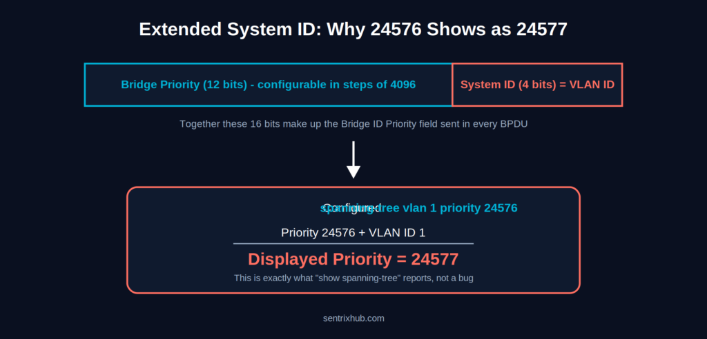
The displayed priority is always your configured value plus the VLAN ID, not a separate number.
STP Root Bridge Election Priority
Priority is the first thing compared, and it carries all the weight. The default on every switch, out of the box, is 32768. Lower values win, all the way down to 0.
Here’s the part that matters most in practice: if every switch in the network is left at the default priority, the election comes down entirely to MAC address, a value nobody chose for network design reasons. It’s effectively a coin flip decided by manufacturing order. Our full walkthrough of the root bridge election process on Cisco switches covers the mechanics of this comparison step by step.
Worth noting: this same priority-then-MAC logic is what runs underneath Per-VLAN Spanning Tree too, just repeated independently for every VLAN. If you’re running PVST and wondering why VLAN 10 and VLAN 20 ended up with different root bridges, how the PVST election process works explains exactly that.
STP Root Bridge Election Example: Step by Step With 3 Switches
This is where the theory turns into something concrete. Picture three switches connected in the same VLAN, none of them manually configured.
| Switch | Priority | MAC Address |
|---|---|---|
| SW1 | 32768 | 00:11:22:33:44:55 |
| SW2 | 32768 | 00:11:22:33:44:11 |
| SW3 | 24576 | 00:11:22:33:44:99 |
Step 1: Compare priority. SW3 has a priority of 24576, lower than SW1 and SW2’s default 32768. That alone settles it. SW3 wins the election immediately, and MAC address never even becomes a factor here, because the comparison stops the moment one switch has a clearly lower priority.
Result: SW3 becomes the root bridge.
It’s worth running this example a second way to see why priority matters so much. If all three switches had been left at the default 32768, SW2 would have won instead, purely because 00:11:22:33:44:11 is numerically the lowest MAC address of the three. Nothing about SW2 makes it a better choice to be root. It just happened to ship with that address. That’s the entire argument for setting priority deliberately rather than leaving it to chance.
Side by side, the difference one configured value makes is easy to see.
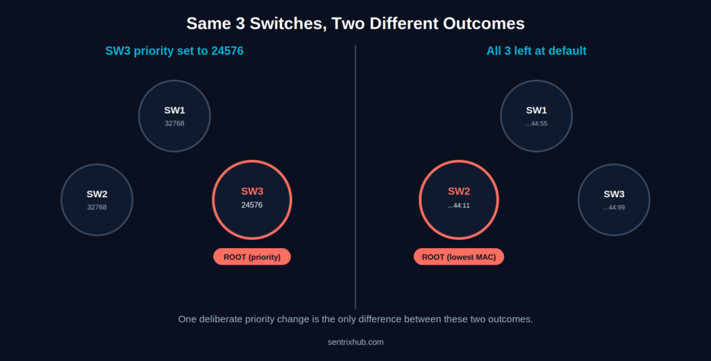
Same three switches, same MAC addresses — the only thing that changes the winner is whether priority was set on purpose.
📌 Worth knowing: SW3 winning here isn’t about SW3 being a better switch. It’s about someone having deliberately set its priority lower. That’s the entire lesson this example is meant to teach.
If you want to test this same skill on more examples, Jeremy’s IT Lab includes several root bridge identification exercises that walk through this exact comparison:
The quiz-style exercises later in the video are worth pausing on. Try identifying the root bridge yourself before the answer reveals, using the same priority-then-MAC-address logic from the walkthrough above.
Root Port Election: What Happens Next
Once the root bridge is settled, every other switch in the topology needs to figure out its own best path back to it. That port is called the root port, and it’s chosen using three criteria in order: lowest path cost, then lowest sender Bridge ID if there’s a tie, then lowest port ID if it’s still tied.
Path cost is tied to link speed, and it’s worth knowing the numbers because they show up constantly in real output: Gigabit Ethernet carries a cost of 4, while an older FastEthernet0 interface carries a cost of 19. A switch with two possible paths to the root will always prefer the lower total cost, even if that means routing through more hops on faster links.
For the complete mechanics of how this decision gets made across a full topology, our root port selection guide with worked examples walks through several scenarios. It’s also worth understanding what STP port states actually mean once roles are assigned, and why only one switch port ends up forwarding on a given segment.
Common Mistakes That Break the Election
The same handful of mistakes show up again and again in networks that weren’t planned deliberately.
Leaving every switch at the default priority is the big one, since it hands control of the topology to MAC address instead of network design. Not configuring a backup root bridge is a close second: if the primary root fails and nothing was set up to take over predictably, the election restarts from scratch and can land somewhere unexpected. Misreading the Bridge ID output, especially the extended system ID offset covered earlier, causes its own share of confusion during troubleshooting.
Laid out as a flow, the order these checks run in is easier to remember.
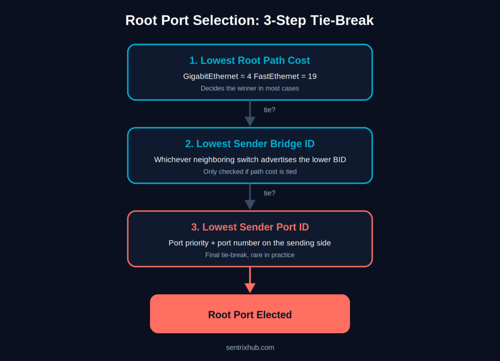
Path cost decides it almost every time — the other two steps only matter in specific topology setups.
Timers compound these problems in ways that aren’t obvious until something goes wrong. Our breakdown of dangerous STP timer mistakes beginners make and why STP port misconfigurations break networks both cover failure patterns that trace back to the same root cause: nothing was configured on purpose.
⚠️ Remember: None of these mistakes require complex root cause analysis to prevent. A single command, setting priority on the switch that should be root, removes the entire category of accidental election outcomes covered in this section.
What Happens When Election Logic Goes Wrong
An accidental root bridge doesn’t usually cause an immediate outage. It causes something quieter and harder to diagnose: inefficient traffic paths, unpredictable convergence after a topology change, and instability that only shows up weeks later when someone adds a new switch to a closet and it happens to win a MAC address tiebreaker nobody was watching for.
If a root port fails outright, the topology has to reconverge, and how gracefully that happens depends heavily on which STP variant is running. Our guides on what happens when an STP root port fails and the serious STP failures RSTP actually prevents go into this in detail, and enterprise STP troubleshooting methods covers how to trace these problems back to their actual cause once symptoms appear.
Redundancy planning at Layer 2 pairs naturally with redundancy thinking elsewhere in the stack. Stateful switchover and enterprise failover stability using alternate ports cover the same underlying goal, keeping traffic flowing through a failure, from a different angle.
Planning For and Documenting STP Risk
Root bridge placement is exactly the kind of thing that’s easy to skip during initial deployment and expensive to fix later. If you’re designing redundancy into a network and want to think through what could realistically go wrong before it happens, mapping it out with our threat model template forces the “what if the wrong switch wins” question onto paper before it becomes a 2 a.m. incident.
And if you’ve already found a misconfigured root bridge during an audit, or you’re documenting STP findings for a client or your own records, our security report template gives that write-up a structure worth using instead of starting from a blank page.
A note on scope: most of the security topics we cover elsewhere on this site, authentication, passwords, API security, don’t have a genuine technical connection to Layer 2 spanning tree, so they’re intentionally left out of this guide rather than forced in for the sake of it.
Frequently Asked Questions
What is an STP root bridge election example?
It’s a worked demonstration showing how switches compare Bridge ID, priority first and MAC address second, to determine which one becomes the root bridge for a VLAN.
What is STP root bridge priority?
A configurable value between 0 and 65535 that determines election weight. Lower values win. The default on every switch is 32768, and with extended system ID enabled, valid values are limited to increments of 4096.
How is the root port selected?
By lowest path cost to the root bridge first, then lowest sender Bridge ID if there’s a tie, then lowest port ID as the final tiebreaker.
What happens if priorities are equal?
The switch with the lowest MAC address becomes the root bridge. This is the default outcome on any network where priority was never manually configured.
Why does show spanning-tree display a different priority than what I configured?
Because of the extended system ID. The displayed value is your configured priority plus the VLAN ID, which is why a priority of 24576 on VLAN 1 shows up as 24577.
Conclusion
The mechanics behind an STP root bridge election example aren’t complicated once you’ve watched them play out: compare priority, fall back to MAC address only if there’s a tie, and the switch with the lowest Bridge ID wins. What actually matters is whether that outcome was designed or left to chance.
Set priority deliberately on the switch that should carry the role, document which switch that is, and the rest of the topology falls into place predictably. Leave it at default, and you’re trusting a MAC address nobody chose to make that decision for you.

Abdul Shakoor writes practical, defensive cybersecurity and networking guides for SentrixHub. He focuses on making API security, mobile app security, authentication, and network concepts simple for beginners and developers.